Hinweis: Auf Grund der zahlreichen internationalen Anfragen zu diesem Projekt bleibt der folgende Beitrag so lange in englischer Sprache verfasst, bis eine gesonderte englische Seite existiert.
Simple ELF-Direct-Receiver
Summary
There are many different ways to receive and record electromagnetic waves in
the range between zero and 50 Hz. Some amateurs directly connect the soundcard of their PC with an appropriate coil and save the received signals with a software sound-recorder as wave or mp3
file. This method has some disadvantages: The strong 50 Hz mains signals which are received involuntary will overdrive the signal if the amplification exceeds a certain amount. So this method
doesn’t permit high amplification values, which are sometimes necessary to detect interesting signals of extremely low level. One good reason to use the receiver presented
here.
Preconditions
Many soundcards show a strong and increasing attenuation from 16 down
to 0 Hz. To build a high quality ELF receiver, you fist should care for an appropriate soundcard: Use an external USB-soundcard with a linear frequency characteristic down to 1 Hz or even lower.
If you can’t find an appropriate type, you can open the housing of the card and replace the serial input capacitor by a bigger one.
The second step to reach the goal consists in using the right recording software. For programmers who are familiar with the question how to access the corresponding software devices in their PC, this may be an interesting challenge, but I recommend a more simple way by using the freely available software SPECTRUM LAB.
The circuit
Now we can care about the receiver circuit itself: It consists of 6
single Operational Amps of the type OP07 which have a very low Offset voltage, which is essential at high gain amplifications.
Input stage
In the circuit diagram, you see a 1:1 input transformer with a lower
cutoff frequency under 1 Hz. This expensive device (available at JENSEN, USA) is only needed when you intend to use the receiver with earth probes (see end of the article). If you only use a
coil, you can omit this device and connect the coil directly to the 100 k serial input resistor.
After a pre-lowpass-filtering and pre-amplifying in the first OpAmp stage, the gain is increased by an inverting amplifier. The amplification can be calculated by dividing the input-output resistor by the pre resistor. With the switch S1 you can set the gain at this stage between (approximately) 5 and 50.
Filter
The three next OpAmps are working together as Sallen-Key lowpass filter with
a cutoff-frequency of 21 Hz. All signals above this value are attenuated with 36 dB per octave, a relatively good value which cares for suppressing even strong mains hum to a non-harmful
level.
Output stage
After the filter stage there is a high pass filter which eliminates an
eventual offset created by the previous stages. As the cutoff frequency is extremely low, it will not influence the received spectrum. The following OpAmp works as amplifier and adding stage at
the same time: By P2, the final amplification can be adapted to the following system (PC). With P1 the offset can be corrected to zero if necessary - or set to another value if required by the
following stage. If you want to protect the following soundcard against high voltages, you may add two diodes as shown in the diagram (optional).
Power supply
The type of power supply you can use depends on your own environment
situation: If you use a set of rechargeable batteries (4 or 5 times 1.2 V in series), I recommend the SIM 0512D power chip which converts a 5 V DC input voltage to a voltage of two times 12
V DC which is needed to feed the OpAmps. If the input voltage is higher than a value of 5 V, you can use the 7805 voltage stabilizer chip at the input (optional).
Coil
The ring-shaped coil I use has a diameter of 40 cm and consists of 4000 turns
of thin isolated copper wire (e.g. 0.25 mm diameter). If the coil is laying flat on the ground, it is sensitive for sources coming from all horizontal directions.
The coil must be kept in an absolute quiet and stable mechanical position because any lowest motion of the coil will create noise caused by the relative movement against the magnetic field of the earth. Keep the coil as far as possible from power cables and big metal masses. In some countries they use alternating high voltage supply for trains (e.g. 16,666 Hz in Germany). Keep a distance of at least a mile or more from railway power lines with alternating currents lower than 20 Hz for good receiving results.
Probes
You also can connect metal sticks (probes) at the input. This requires the
input transformer mentioned above for safety reasons (vagabounding currents).
Attention - Danger: The receiver and the PC connected to it must be completely electrically isolated against the ground where you put the probes in if at least one device is supplied by mains. If you use the probes in a distance of one to five meters, you can receive the same and sometimes also different signals as by coil.
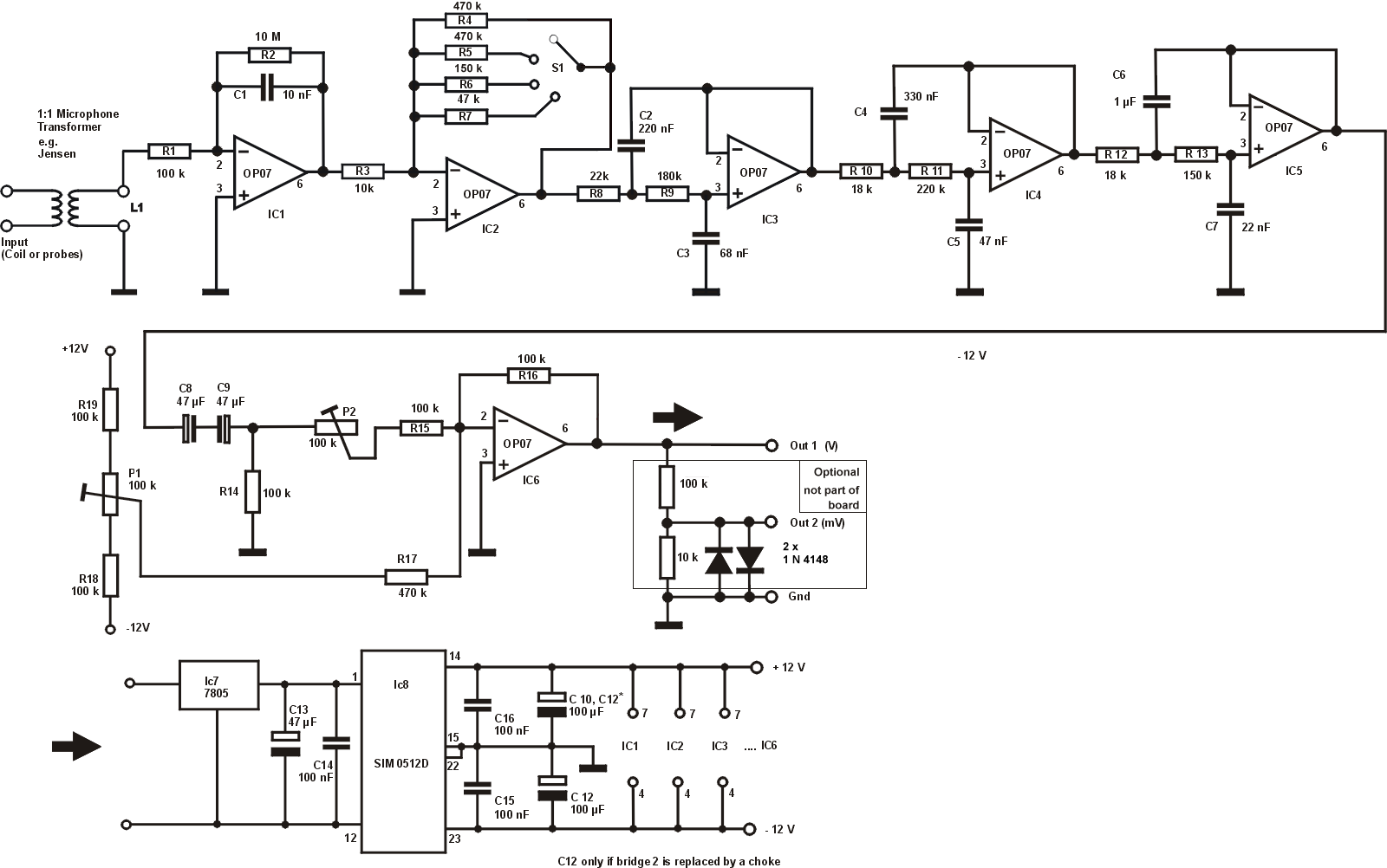

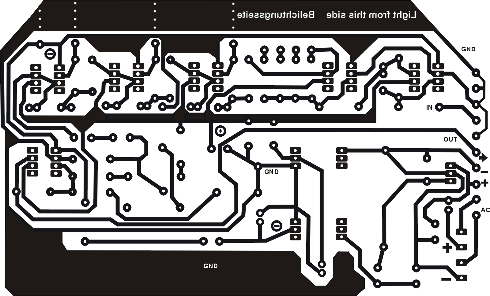
This image serves only as overlook. See more details of the circuit in the download version.

This image serves only as overlook. Pleasse use the download version as original for creating the transparent photo layer. The layout is shown from the component view.
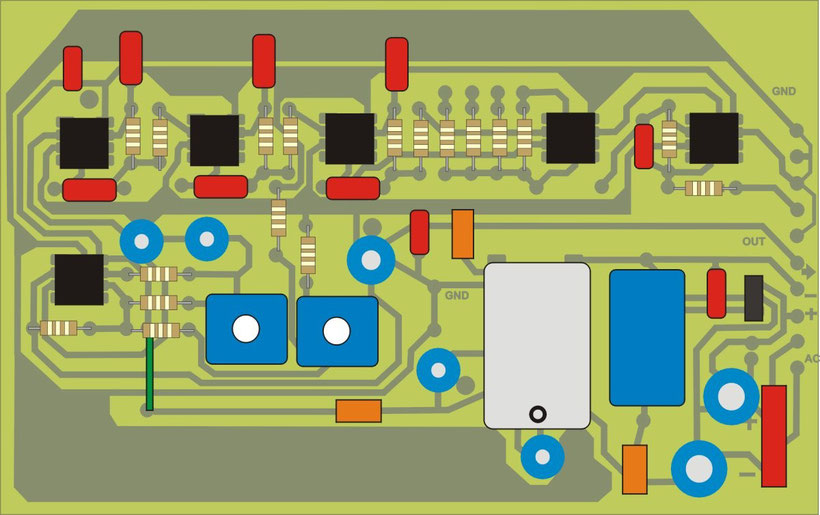
View from component side
(red = capacitors / black = OpAmps / blue = capacitors or trimmers / white: DC-DC converter / orange rectangles: Use wire bridges or chokes of an appropriate inductivity).
At the lower right corner an additional bridge rectifier can be mounted if only an AC source is available. If you use a DC supply source, this spare part can be omitted.
Orange Rectangles: Use wire bridges or chokes of an appropriate inductivity.
More detailed mounting scheme will follow.